In the embedded systems/SoCs, Watchdog Timer(WDT) is the basic, subtle and essential circuit/ic. No matter, how good you write your firmware/software. There are always unexpected situations like your program may stick in an infinite loop, hung somewhere or hardware burn-out/failure. To combat these unexpected situations, we need some circuitry that keeps monitoring the main system/application and in case of unexpected events, it restarts the system.
Even the windows-like operating system use the watchdog timer. But with more sophisticated software & hardware i.e. window’s Blue Screen of Death (BSoD).
WDT comes as an integral part of Microcontrollers/SoCs or you may also get it as a separate chip.
Contents
What Is Watchdog Timer?
- A Watchdog Timer(WDT) is a piece of hardware that uses to automatically detect software anomalies. And reset the processor if any occur.
- Generally speaking, a watchdog timer is kind of timer/counter that counts down from some preset value to zero.
- The embedded software selects the counter’s initial value and periodically restarts the timer before it reaches zero.
- If WDT reaches to zero, software presumes to malfunction. And the processor’s reset signal asserted. The processor will restart as if a human operator had cycled the power.
Block Diagram
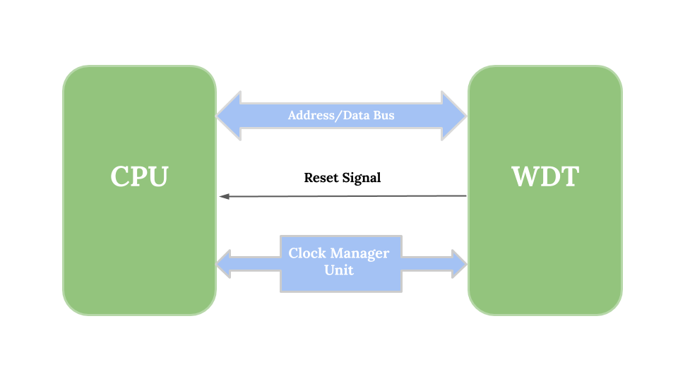
- Above figure shows a typical arrangement of external WDT to CPU.
- Depending upon vendors & types, Watchdog Timer has numbers of CPU programmable memory-mapped registers.
- CPU receives the reset signal from WDT to identify the timeout condition.
- There could be many other interfaces as well(depending upon microcontroller or chip vendor) but I have taken a minimalistic example to show boiled down interfacing.
Programming Procedure
- Although this is a subjective matter as there are many SoCs in the market and they use a different type of watchdog timer but the overall concept is the same more or less. Following is a general procedure to program the WDT:
const uint32_t timeout_cnt = 0x12345678;

main()
{
    hw_init();
    wdt_init(timeout_cnt);

    for (;;)
    {
        extract_data_from_sensors(); // task 1: may take 800 micro-seconds
        handle_motor_control();      // task 2: may take 6 milli-seconds
        display_status();            // task 3: may take 2 milli-seconds

        // ... some other tasks

        re_set_wdt();                // set timeout of 8 milli-seconds approximately
    }
}
- In bare-metal software, we generally have a single main loop comprising of all the tasks & we simply put the watchdog reset mechanism at the end of this loop as you can see above.
- But before reset mechanism kick-in, we have to initialize WDT register related to control, tick count, etc with proper values which usually carried out in hardware initialization phase or in the start-up of application.
- Calculation of tick count includes
- Approximate time consumed by all the tasks
- Plus some buffer amount of time(for speed variation due to other parameters like temperature, etc).
- On top of this, WDT count register value(i.e. tick count) decided with the help of WDT input frequency(and Prescaler if used any).
How Does Watchdog Timer Work?
- As I said earlier, WDT is basically a timer. So it keeps counting down till zero. As long as all the tasks completed in approximate precomputed time before tick count reaches zero. WDT repeatedly reinitialize with tick count at the end of the loop(as shown in the code snippet above).
- But in some unexpected situations, there might be chances that some task stuck, hangs or taking a longer time than usual. In such cases timer expires(means tick count reaches to zero) & reset signal asserts to CPU.
- CPU resets(as like you just power-on) and your code again start executing from main(precisely program counter set to starting of 1st instruction of your code).
- Although, this is not necessarily true that the reset signal directly driven to CPU. Because in most of the complex(or I would say advanced) embedded systems which have multicore & separate reset/fault management unit. There has an interconnect circuitry to route this kind of signals to appropriate CPU or reset/fault management block to check criticality state of the system before to reset it.
Issue With Traditional Watchdog Timer
- Older/normal watchdogs are only watching upon overrun condition like some task taking longer time, hangs, stuck, etc.
- But what if some component detached from the system, burn-out or giving false results without process or doing anything meaningful. In such cases, your watchdog timer will keep resetting too frequently.
- This is also underrun & an error-prone scenario that should be checked too. And hence the Window Watchdog Timer:
Window Watchdog Timer
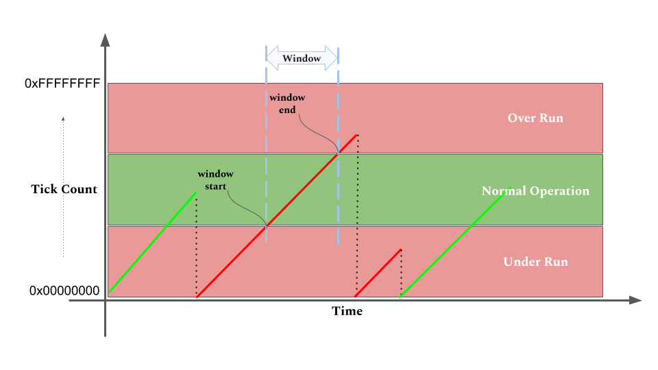
- Window Watchdog Timer not only checks for overrunning. But also look upon underrun condition with the help of two tick count registers rather than one.
- Start/Low tick count register used to measure start point of window & End/Low used to measure the endpoint of the window.
- If all the task complete within this(marked in green above) time frame/window then only WDT re-sets. Otherwise, it asserts the reset signal.
- See this microchip or maxim’s WWDT for example.
Summary
A watchdog timer is a fail-safe hardware mechanism that resets the microcontroller when its timer expires/reaches-zero.
– Watchdog timer keeps counting down till zero.
– As long as all the tasks completed in approximate precomputed time before tick count reaches zero.
– WDT repeatedly reinitialize with tick count at the end of the loop(as shown in the code snippet example above).
– If it reaches zero, software presumes to malfunction. And the processor’s reset signal asserted.
Watchdog timer prevents software malfunction & provide soft real-time behaviour for embedded systems/SoC.
Watchdog timers in modern embedded systems/SoCs are way more complex than they have to be in earlier days:
– Have Prescaler to divide clock to increase tick count period,
– Also, use window mode as we discussed above,
– Uses more than one reset signal to indicate the type of fault to CPU/fault-generator,
– Able to detect sleep mode of CPUs to shut down its operation,
– Also tracks the state of system SFRs,
– May have an interface to Power-On Reset (POR), Brown Out Reset (BOR), Low Power Brown Out Reset (LPBOR, etc) for some advanced functionality.
Do you like it☝️? Get such articles directly into the inbox…!?